
Rishiraj Adhikary
5 min read.
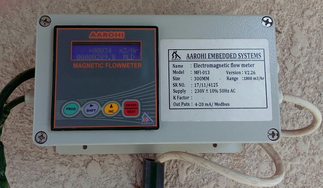
Water scarcity problem is highly prevalent in western India. Studies estimate that 20-35% of the total water flow is wasted due to leakages in the network, which if timely rectified can reduce wastage by more than 90%. This necessities the need to monitor the water flow using sensing infrastructure. Water flow sensors are typically placed in between water piper by physically cutting them. Some of these flow sensors are even connected to a flow meter. Flow sensors output data as a current. Data in the form of current does not attenuate over a long distance, unlike voltage. The output current typically ranges from 4mA to 20mA.
We have to make the flow sensor data available to a microprocessor/microcontroller so that we can further store the data in a database and process it. We used Raspberry Pi for this purpose. But devices such as Raspberry Pi takes voltage as an input signal and not current. Thus, we need a current to voltage converter. We used an off the shelf module (XY-IT0V) that converts 4-20mA current to 0-5V/3.3V signal.
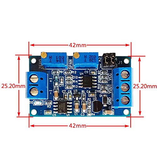
Current to Voltage Converter: The current to voltage converter module had minimal documentation online. According to the documentation, the output voltage never exceeds the input supply voltage. Also, at 0mA current, the circuit should ideally show 0V. At 40mA current, the circuit should ideally show the external voltage value. We powered this circuit with 5V and tested with current source generated in our lab. We observed that at 0mA current, the the output voltage fluctuates between 0.20-0.28V. At 40mA, the voltage value fluctuates between 4.8-5.5V. There are two potentiometers on the module, namely ZERO and SPAN potentiometers. When the current input is the minimum (0mA or 4mA), we are suppose to adjust the ZERO potentiometer so that the output voltage is the minimum (0.0V or other voltage). When the current input is at maximum (40mA or other), we need to adjust the SPAN potentiometer so that the output voltage is the maximum (3.3V or 5V or 10V).
Once we have the voltage signal (in 0V to 5V range), the next immediate step was to convert this Analog signal Digital value. Since the Raspberry Pi does not have a on-board ADC, we used the classic ADS1115 ADC for this purpose. It has a very good documentation online and we explain it in brief here.
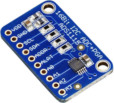
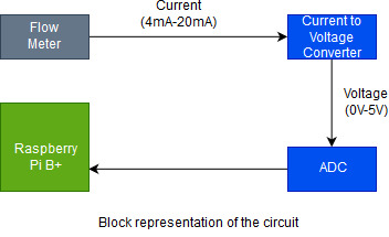
Analog to Digital Conver (ADS1115): The ADS1115 is a 15 bit resolution ADC. It works on the I2C protocol and hence we can connect upto 4 analog input device to this sensor with each having a different address. For our experiment, we connected the output voltage to the ADC pin A0. We wire up the ADC with the Raspberry Pi Model B+ as shown in the figure below. The A0 pin of ADC is connected to the voltage output from the current to voltage converter module.
Raspberry Pi: Once the connections are set up, we need to configure the Raspberry Pi as explained below.
- Update the RPi to run the latest linux
sudo apt-get updatesudo apt-get upgradesudo pip3 install --upgrade setuptools or sudo apt-get install python3-pip
- Enable I2C.
- Install I2C utility:
sudo apt-get install -y python-smbus and sudo apt-get install -y i2c-tools - Run
sudo raspi-config, go to ‘Interfacing Option’ and enable I2C - Once done, reboot!.
sudo reboot. - Test the I2C interface,
sudo i2cdetect -y 1 - The result of 4) in the terminal should show the I2C address in Use. (Should be 0x48 in our case)
- Install I2C utility:
- Make sure Rpi is using Python3 and Pip3
- Install the following libraries
pip3 install RPI.GPIOpip3 install adafruit-blinka
- Test if everything is running by testing your Pi with blinkatest.py
- Install the library for ADS1115: sudo pip3 install adafruit-circuitpython-ads1x15
- Run the file, testADCv1.py
Below is the code for blinktest.py
import board
import digitalio
import busio

print("Hello blinka!")

# Try to great a Digital input
pin = digitalio.DigitalInOut(board.D4)
print("Digital IO ok!")

# Try to create an I2C device
i2c = busio.I2C(board.SCL, board.SDA)
print("I2C ok!")

# Try to create an SPI device
spi = busio.SPI(board.SCLK, board.MOSI, board.MISO)
print("SPI ok!")

print("done!")
Below is the code for testADCv1.py
import board
import busio
i2c = busio.I2C(board.SCL, board.SDA)

import adafruit_ads1x15.ads1115 as ADS

from adafruit_ads1x15.analog_in import AnalogIn

ads = ADS.ADS1115(i2c)
chan = AnalogIn(ads, ADS.P0)
print(chan.value, chan.voltage)
On running the file, we should see the ADC value and the voltage value on the screen. We later created a MySQL database on the Raspberry Pi to store the ADC data periodically after every 5 minutes. We can execute the Python Script every 5 minutes using the cron job scheduler of the OS in the Raspberry Pi.
The complete circuit just before deployment.

Rishiraj Adhikary
Twitter
Github
Website
Blog Posts
Rishiraj is a Research Assistant in CS department at IIT Gandhinagar. He is working under Prof. Nipun Batra.